Product Description
Product Description
MAIN FEATURES:
1) Made of high quality material, non-rusting;Both flange and foot mounting available and suitable for all-round installation
2) Large output torque and high radiating efficiency
3)Precise grinding helical gear with Smooth running and low noise, no deformation,can work long time in dreadful condition
4)Nice appearance, durable service life and small volume, compact structure
5)Both 2 and 3 stage available with wide ratio range from 5 to 200
6)Different output shaft diameter available -40-50mm
7)Modular construction enlarge ratio from 5 to 1400
MAIN MATERIALS:
1)housing with aluminium alloyand cast iron material;
2)Output Shaft Material:20CrMnTi
3)Good quality no noise bearings to keep long service life
4)High performance oil seal to prevent from oil leakage
APPLICATIONS:
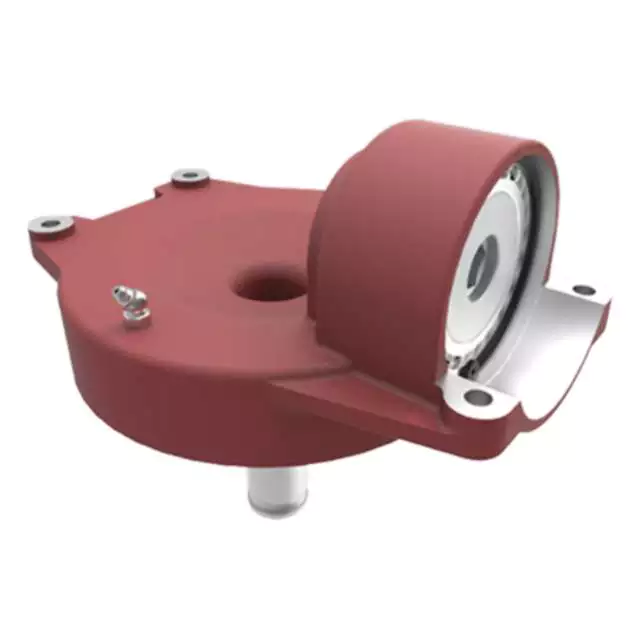
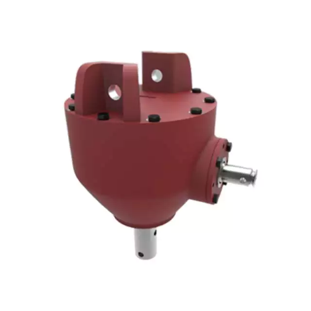
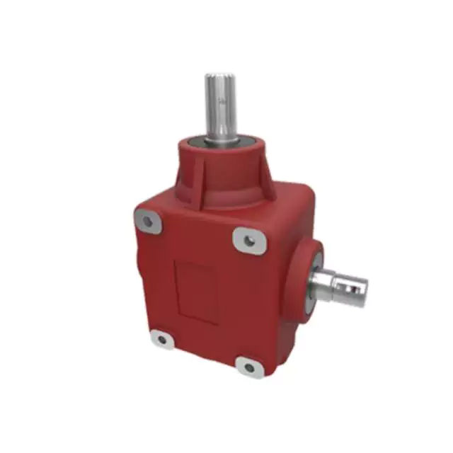
G3 Series helical gear motor are wide used for all kinds of automatic equipment, such as chip removal machine, conveyor, packaging equipment, woodworking machinery, farming equipment, slurry scraper ,dryer, mixer and so on.
Detailed Photos
Product Parameters
| (n1=1400r/min 50hz) | |||||||||||||||||
| norminal ratio | 5 | 10 | 15 | 20 | 25 | 30 | 40 | 50 | 60 | 80 | 100 | 100 | 120 | 160 | 200 | ||
| 0.1kw | output shaft | Ø18 | Ø22 | ||||||||||||||
| n2* (r/min) | 282 | 138 | 92 | 70 | 56 | 46 | 35 | 28 | 23 | 18 | 14 | – | 11 | 9 | 7 | ||
| M2(Nm) | 50hz | 3.2 | 6.5 | 9.8 | 12.9 | 16.1 | 19.6 | 25.7 | 31.1 | 37.5 | 49.5 | 62.9 | – | 76.1 | 100.7 | 125.4 | |
| 60hz | 3 | 5 | 8 | 11 | 13 | 17 | 21 | 26 | 31 | 41 | 52 | – | 63 | 84 | 105 | ||
| Fr1(N) | 588 | 882 | 980 | 1180 | 1270 | 1370 | 1470 | 1570 | 2160 | 2450 | 2450 | 2450 | 2450 | 2450 | 2450 | ||
| Fr2(N) | 176 | ||||||||||||||||
| norminal ratio | 5 | 10 | 15 | 20 | 25 | 30 | 40 | 50 | 60 | 80 | 100 | 100 | 120 | 160 | 200 | ||
| 0.2kw | output shaft | Ø18 | Ø22 | Ø28 | |||||||||||||
| n2* (r/min) | 282 | 138 | 92 | 70 | 56 | 45 | 35 | 29 | 23 | 18 | 14 | 13 | 12 | 8 | 7 | ||
| M2(Nm) | 50hz | 6.5 | 12.6 | 19.1 | 26.3 | 32.6 | 38.9 | 50.4 | 63 | 75.6 | 100.8 | 103.9 | 125.4 | 150 | 200.4 | 250.7 | |
| 60hz | 5.4 | 10.5 | 16.6 | 21.9 | 27.1 | 32.4 | 42 | 52.5 | 63 | 84 | 86.6 | 104.5 | 125 | 167 | 208.9 | ||
| Fr1(N) | 588 | 882 | 980 | 1180 | 1270 | 1760 | 1860 | 1960 | 2160 | 2450 | 2450 | 2840 | 3330 | 3430 | 3430 | ||
| Fr2(N) | 196 | ||||||||||||||||
| norminal ratio | 5 | 10 | 15 | 20 | 25 | 30 | 40 | 50 | 60 | 80 | 100 | 100 | 120 | 160 | 200 | ||
| 0.4kw | output shaft | Ø22 | Ø28 | Ø32 | |||||||||||||
| n2* (r/min) | 288 | 144 | 92 | 72 | 58 | 47 | 36 | 29 | 24 | 18 | 14 | 14 | 12 | 9 | 7 | ||
| M2(Nm) | 50hz | 12.9 | 25 | 38.6 | 51.4 | 65.4 | 78.2 | 100.7 | 125.4 | 150 | 200.4 | 206.8 | 250.7 | 301.1 | 400.7 | 461.8 | |
| 60hz | 10.7 | 20.8 | 32.1 | 42.9 | 54.5 | 65.2 | 83.9 | 104.5 | 125 | 167 | 172.3 | 208.9 | 250.9 | 333.9 | 384.8 | ||
| Fr1(N) | 882 | 1180 | 1370 | 1470 | 1670 | 2550 | 2840 | 3140 | 3430 | 3430 | 3430 | 4900 | 5880 | 5880 | 5880 | ||
| Fr2(N) | 245 | ||||||||||||||||
| norminal ratio | 5 | 10 | 15 | 20 | 25 | 30 | 40 | 50 | 60 | 80 | 100 | 100 | 120 | 160 | 200 | ||
| 0.75kw | output shaft | Ø28 | Ø32 | Ø40 | |||||||||||||
| n2* (r/min) | 278 | 140 | 94 | 69 | 58 | 46 | 35 | 29 | 24 | 18 | 14 | 14 | 11 | 9 | 7 | ||
| M2(Nm) | 50hz | 24.6 | 48.2 | 72.9 | 97.5 | 122.1 | 145.7 | 187.5 | 235.7 | 282.9 | 376.1 | 387.9 | 439 | 527 | 703 | 764 | |
| 60hz | 20.5 | 40.2 | 60.7 | 81.3 | 201.8 | 121.4 | 156.3 | 196.4 | 235.7 | 313.4 | 323.2 | 366 | 439 | 585 | 732 | ||
| Fr1(N) | 1270 | 1760 | 2160 | 2350 | 2450 | 4571 | 4210 | 4610 | 5490 | 5880 | 5880 | 7060 | 7060 | 7060 | 7060 | ||
| Fr2(N) | 294 | ||||||||||||||||
| norminal ratio | 5 | 10 | 15 | 20 | 25 | 30 | 40 | 50 | 60 | 80 | 100 | 100 | 120 | 160 | 200 | ||
| 1.5kw | output shaft | Ø32 | Ø40 | Ø50 | |||||||||||||
| n2* (r/min) | 280 | 140 | 93 | 70 | 55 | 47 | 34 | 27 | 24 | 17 | 14 | 13 | 12 | 8 | 7 | ||
| M2(Nm) | 50hz | 48.2 | 97.5 | 145.7 | 193.9 | 242.1 | 272 | 351 | 439 | 527 | 703 | 724 | 878 | 1060 | 1230 | 1230 | |
| 60hz | 40.2 | 81.3 | 121.4 | 161.6 | 201.8 | 226 | 293 | 366 | 439 | 585 | 603 | 732 | 878 | 1170 | 1230 | ||
| Fr1(N) | 1760 | 2450 | 2840 | 3230 | 3820 | 5100 | 5880 | 7060 | 7060 | 7060 | 7060 | 9800 | 9800 | 9800 | 9800 | ||
| Fr2(N) | 343 | ||||||||||||||||
| norminal ratio | 5 | 10 | 15 | 20 | 25 | 30 | 40 | 50 | 60 | 80 | 100 | ||||||
| 2.2kw | output shaft | Ø40 | Ø50 | ||||||||||||||
| n2* (r/min) | 272 | 136 | 95 | 68 | 54 | 45 | 36 | 28 | 24 | 18 | 14 | ||||||
| M2(Nm) | 50hz | 67 | 133 | 200 | 266 | 332 | 399 | 515 | 644 | 773 | 1571 | 1230 | |||||
| 60hz | 56 | 111 | 167 | 221 | 277 | 332 | 429 | 537 | 644 | 858 | 1080 | ||||||
| Fr1(N) | 2160 | 3140 | 3530 | 4571 | 4700 | 6960 | 7250 | 8620 | 9800 | 9800 | 9800 | ||||||
| Fr2(N) | 392 | ||||||||||||||||
Outline and mounting dimension:
| G3FM: THREE PHASE GEAR MOTOR WITH FLANGE (n1=1400r/min) | ||||||||||||||||||||
| Power kw | output shaft | ratio | A | F | I | J | M | O | O1 | P | Q | R | S | T | U | W | X | Y | Y1 | |
| standard | brake | |||||||||||||||||||
| 0.1kw | Ø18 | 5–30-40-50 | 236 | 270 | 192.5 | 11 | 16.5 | 170 | 4 | 10 | 30 | 145 | 35 | 18 | 20.5 | 129 | 6 | 157 | 80 | 81 |
| Ø22 | -160-200 | 262 | 296 | 197.5 | 11 | 19 | 185 | 4 | 12 | 40 | 148 | 47 | 22 | 24.5 | 129 | 6 | 171.5 | 89.5 | 83.5 | |
| 0.2kw | Ø18 | 5- | 267 | 270 | 192.5 | 11 | 16.5 | 170 | 4 | 10 | 30 | 145 | 35 | 18 | 20.5 | 129 | 6 | 161 | 80 | 81 |
| Ø22 | -80-100 | 293 | 296 | 197.5 | 11 | 19 | 185 | 4 | 12 | 40 | 148 | 47 | 22 | 24.5 | 129 | 6 | 171.5 | 89.5 | 83.5 | |
| Ø28 | 306 | 309.5 | 208.5 | 11 | 23.5 | 215 | 4 | 15 | 45 | 170 | 50 | 28 | 31 | 129 | 8 | 198.5 | 105.5 | 88 | ||
| 0.4kw | Ø22 | 5- | 314 | 324.5 | 204 | 11 | 19 | 185 | 4 | 12 | 40 | 148 | 47 | 22 | 24.5 | 139 | 6 | 171.5 | 89.5 | 88.5 |
| Ø28 | -80-100 | 330 | 337.5 | 215 | 11 | 23.5 | 215 | 4 | 15 | 45 | 170 | 50 | 28 | 31 | 139 | 8 | 198.5 | 105.5 | 93 | |
| Ø32 | 349 | 357 | 229.5 | 13 | 28.5 | 250 | 4 | 15 | 55 | 180 | 60 | 32 | 35 | 139 | 10 | 234 | 126 | 98 | ||
| 0.75kw | Ø28 | 5- | 350.5 | 343.5 | 227.5 | 11 | 23.5 | 215 | 4 | 15 | 45 | 170 | 50 | 28 | 31 | 159 | 8 | 198.5 | 105.5 | 103 |
| Ø32 | -80-100 | 379.5 | 387 | 242 | 13 | 28.5 | 250 | 4 | 15 | 55 | 180 | 60 | 32 | 35 | 159 | 10 | 234 | 126 | 108 | |
| Ø40 | 401.5 | 408.5 | 270 | 18 | 34 | 310 | 5 | 18 | 65 | 230 | 71 | 40 | 43 | 185 | 12 | 284 | 149 | 126.5 | ||
| 1.5kw | Ø32 | 5- | 420.5 | 441 | 254 | 13 | 28.5 | 250 | 5 | 15 | 55 | 180 | 60 | 32 | 35 | 185 | 10 | 234 | 126 | 121 |
| Ø40 | -80-100 | 457.5 | 478 | 270 | 18 | 34 | 310 | 5 | 18 | 65 | 230 | 71 | 40 | 43 | 185 | 12 | 284 | 149 | 126.5 | |
| Ø50 | 485.5 | 506 | 300 | 22 | 40 | 360 | 5 | 25 | 75 | 270 | 83 | 50 | 53.5 | 185 | 14 | 325 | 173.5 | 132.5 | ||
| 2.2kw | Ø40 | 5- | 466.5 | 487 | 270 | 18 | 34 | 310 | 5 | 18 | 65 | 230 | 71 | 40 | 43 | 185 | 12 | 284 | 149 | 126.5 |
| Ø50 | -80-100 | 510.5 | 531 | 300 | 22 | 40 | 360 | 5 | 25 | 75 | 270 | 83 | 50 | 53.5 | 185 | 14 | 325 | 173.5 | 132.5 | |
| G3LM: THREE PHASE GEAR MOTOR WITH FOOT (n1=1400r/min) | ||||||||||||||||||||
| Power kw | output shaft | ratio | A | D | E | F | J | G | H | K | P | S | T | U | V | W | X | Y | Y1 | |
| standard | brake | |||||||||||||||||||
| 0.1kw | Ø18 | 5–30-40-50 | 236 | 270 | 40 | 110 | 135 | 16.5 | 65 | 9 | 45 | 30 | 18 | 20.5 | 129 | 183 | 6 | 133 | 85 | 10 |
| Ø22 | -160-200 | 262 | 296 | 65 | 130 | 155 | 19 | 90 | 11 | 55 | 40 | 22 | 24.5 | 129 | 193 | 6 | 139.5 | 90 | 12 | |
| 0.2kw | Ø18 | 5- | 267 | 270 | 40 | 110 | 135 | 16.5 | 65 | 9 | 45 | 30 | 18 | 20.5 | 129 | 183 | 6 | 133 | 85 | 10 |
| Ø22 | -80-100 | 293 | 296 | 65 | 130 | 155 | 19 | 90 | 11 | 55 | 40 | 22 | 24.5 | 129 | 193 | 6 | 139.5 | 90 | 12 | |
| Ø28 | 306 | 309.5 | 90 | 140 | 175 | 23.5 | 125 | 11 | 65 | 45 | 28 | 31 | 129 | 203 | 8 | 170 | 110 | 15 | ||
| 0.4kw | Ø22 | 5- | 314 | 324.5 | 65 | 130 | 155 | 19 | 90 | 11 | 55 | 40 | 22 | 24.5 | 139 | 199.5 | 6 | 141.5 | 90 | 12 |
| Ø28 | -80-100 | 330 | 337.5 | 90 | 140 | 175 | 23.5 | 125 | 11 | 65 | 45 | 28 | 31 | 139 | 210 | 8 | 170 | 110 | 15 | |
| Ø32 | 349 | 357 | 130 | 170 | 208 | 28.5 | 170 | 13 | 70 | 55 | 32 | 35 | 139 | 226 | 10 | 198 | 130 | 18 | ||
| 0.75kw | Ø28 | 5- | 350.5 | 343.5 | 90 | 140 | 175 | 23.5 | 125 | 11 | 65 | 45 | 28 | 31 | 159 | 222 | 8 | 170 | 110 | 15 |
| Ø32 | -80-100 | 379.5 | 387 | 130 | 170 | 208 | 28.5 | 170 | 13 | 70 | 55 | 32 | 35 | 159 | 238.5 | 10 | 198 | 130 | 18 | |
| Ø40 | 401.5 | 408.5 | 150 | 210 | 254 | 34 | 196 | 15 | 90 | 65 | 40 | 43 | 185 | 249 | 12 | 230 | 150 | 20 | ||
| 1.5kw | Ø32 | 5- | 420.5 | 441 | 130 | 170 | 208 | 28.5 | 170 | 13 | 70 | 55 | 32 | 35 | 185 | 250.5 | 10 | 198 | 130 | 18 |
| Ø40 | -80-100 | 457.5 | 478 | 150 | 210 | 254 | 34 | 196 | 15 | 90 | 65 | 40 | 43 | 185 | 260 | 12 | 230 | 150 | 20 | |
| Ø50 | 485.5 | 506 | 160 | 230 | 290 | 40 | 210 | 18 | 100 | 75 | 50 | 53.5 | 185 | 288 | 14 | 265 | 170 | 25 | ||
| 2.2kw | Ø40 | 5- | 466.5 | 487 | 150 | 210 | 254 | 34 | 196 | 15 | 90 | 65 | 40 | 43 | 185 | 260 | 12 | 230 | 150 | 20 |
| Ø50 | -80-100 | 510.5 | 531 | 160 | 230 | 290 | 40 | 210 | 18 | 100 | 75 | 50 | 53.5 | 185 | 288 | 14 | 265 | 170 | 25 | |
| G3FS: IEC GEAR REDUCER WITH FOOT (n1=1400r/min) | |||||||||||||||||||||||||
| Power kw | output shaft | ratio | A | B | C | F | I | J | L | M | N | O | O1 | P | Q | R | S | S1 | T | T1 | W | W1 | X | Y | Y1 |
| 0.12kw | Ø18 | 5–30-40-50 | 147 | 95 | 115 | 154 | 11 | 16.5 | 4.5 | 170 | 140 | 4 | 10 | 30 | 145 | 35 | 18 | 11 | 20.5 | 12.8 | 6 | 4 | 163 | 80 | 86.5 |
| Ø22 | -160-200 | 173 | 95 | 115 | 164 | 11 | 19 | 4.5 | 185 | 140 | 4 | 12 | 40 | 148 | 47 | 22 | 11 | 24.5 | 12.8 | 6 | 4 | 171.5 | 89.5 | 89 | |
| 0.18kw | Ø18 | 5- | 147 | 95 | 115 | 154 | 11 | 16.5 | 4.5 | 170 | 140 | 4 | 10 | 30 | 145 | 35 | 18 | 11 | 20.5 | 12.8 | 6 | 4 | 163 | 80 | 86.5 |
| Ø22 | -80-100 | 173 | 95 | 115 | 164 | 11 | 19 | 4.5 | 185 | 140 | 4 | 12 | 40 | 148 | 47 | 22 | 11 | 24.5 | 12.8 | 6 | 4 | 171.5 | 89.5 | 89 | |
| Ø28 | 186.5 | 95 | 115 | 186 | 11 | 23.5 | 4.5 | 215 | 140 | 4 | 15 | 45 | 170 | 50 | 28 | 11 | 31 | 12.8 | 8 | 4 | 198.5 | 105.5 | 93.5 | ||
| 0.37kw | Ø22 | 5- | 181.5 | 110 | 130 | 164 | 11 | 19 | 4.5 | 185 | 160 | 4 | 12 | 40 | 148 | 47 | 22 | 14 | 24.5 | 16.3 | 6 | 5 | 201 | 89.5 | 99 |
| Ø28 | -80-100 | 198 | 110 | 130 | 186 | 11 | 23.5 | 4.5 | 215 | 160 | 4 | 15 | 45 | 170 | 50 | 28 | 14 | 31 | 16.3 | 8 | 5 | 198.5 | 105.5 | 103.5 | |
| Ø32 | 216.5 | 110 | 130 | 215 | 13 | 28.5 | 4.5 | 250 | 160 | 4 | 15 | 55 | 180 | 60 | 32 | 14 | 35 | 16.3 | 10 | 5 | 234 | 126 | 108.5 | ||
| 0.75kw | Ø28 | 5- | 206.5 | 130 | 165 | 185 | 11 | 23.5 | 4.5 | 215 | 200 | 4 | 15 | 45 | 170 | 50 | 28 | 19 | 31 | 21.8 | 8 | 6 | 216.5 | 105.5 | 123.5 |
| Ø32 | -80-100 | 235 | 130 | 165 | 215 | 13 | 28.5 | 4.5 | 250 | 200 | 4 | 15 | 55 | 180 | 60 | 32 | 19 | 35 | 21.8 | 10 | 6 | 236.5 | 126 | 128.5 | |
| Ø40 | 260.5 | 130 | 165 | 270 | 18 | 34 | 4.5 | 310 | 200 | 5 | 18 | 65 | 230 | 71 | 40 | 19 | 43 | 21.8 | 12 | 8 | 284 | 149 | 134 | ||
| 1.5kw | Ø32 | 5- | 252 | 130 | 165 | 215 | 13 | 28.5 | 4.5 | 250 | 200 | 5 | 15 | 55 | 180 | 60 | 32 | 24 | 35 | 27.3 | 10 | 8 | 236.5 | 126 | 128.5 |
| Ø40 | -80-100 | 293.5 | 130 | 165 | 270 | 18 | 34 | 4.5 | 310 | 200 | 5 | 18 | 65 | 230 | 71 | 40 | 24 | 43 | 27.3 | 12 | 8 | 284 | 149 | 134 | |
| Ø50 | 321.5 | 130 | 165 | 300 | 22 | 40 | 4.5 | 360 | 200 | 5 | 25 | 75 | 270 | 83 | 50 | 24 | 53.5 | 27.3 | 14 | 8 | 323.5 | 173.5 | 140 | ||
| 2.2kw | Ø40 | 5- | 290 | 180 | 215 | 270 | 18 | 34 | 5.5 | 310 | 250 | 5 | 18 | 65 | 230 | 71 | 40 | 28 | 43 | 31.3 | 12 | 8 | 284 | 149 | 134 |
| Ø50 | -80-100 | 334 | 180 | 215 | 300 | 22 | 40 | 5.5 | 360 | 250 | 5 | 25 | 75 | 270 | 83 | 50 | 28 | 53.5 | 31.3 | 14 | 8 | 323.5 | 173.5 | 140 | |
| G3LS: IEC GEAR REDUCER WITH FOOT (n1=1400r/min) | |||||||||||||||||||||||||
| Power kw | output shaft | ratio | A | B | C | D | E | F | G | H | J | K | L | N | P | S | S1 | T | T1 | W | W1 | X | Y | Y1 | Z |
| 0.12kw | Ø18 | 5–30-40-50 | 147 | 95 | 115 | 40 | 110 | 135 | 65 | 9 | 16.5 | 45 | 4.5 | 140 | 30 | 18 | 11 | 20.5 | 12.8 | 6 | 4 | 138.5 | 85 | 10 | M8 |
| Ø22 | -160-200 | 173 | 95 | 115 | 65 | 130 | 154 | 90 | 11 | 19 | 55 | 4.5 | 140 | 40 | 22 | 11 | 24.5 | 12.8 | 6 | 4 | 141 | 90 | 12 | M8 | |
| 0.18kw | Ø18 | 5- | 147 | 95 | 115 | 40 | 110 | 135 | 65 | 9 | 16.5 | 45 | 4.5 | 140 | 30 | 18 | 11 | 20.5 | 12.8 | 6 | 4 | 138.5 | 85 | 10 | M8 |
| Ø22 | -80-100 | 173 | 95 | 115 | 65 | 130 | 154 | 90 | 11 | 19 | 55 | 4.5 | 140 | 40 | 22 | 11 | 24.5 | 12.8 | 6 | 4 | 141 | 90 | 12 | M8 | |
| Ø28 | 186.5 | 95 | 115 | 90 | 140 | 175 | 125 | 11 | 23.5 | 65 | 4.5 | 140 | 45 | 28 | 11 | 31 | 12.8 | 8 | 4 | 170 | 110 | 15 | M8 | ||
| 0.37kw | Ø22 | 5- | 181.5 | 110 | 130 | 65 | 130 | 154 | 90 | 11 | 19 | 55 | 4.5 | 160 | 40 | 22 | 14 | 24.5 | 16.3 | 6 | 5 | 151 | 90 | 12 | M8 |
| Ø28 | -80-100 | 198 | 110 | 130 | 90 | 140 | 175 | 125 | 11 | 23.5 | 65 | 4.5 | 160 | 45 | 28 | 14 | 31 | 16.3 | 8 | 5 | 170 | 110 | 15 | M8 | |
| Ø32 | 216.5 | 110 | 130 | 130 | 170 | 208 | 170 | 13 | 28.5 | 70 | 4.5 | 160 | 55 | 32 | 14 | 35 | 16.3 | 10 | 5 | 198 | 130 | 18 | M8 | ||
| 0.75kw | Ø28 | 5- | 206.5 | 130 | 165 | 90 | 140 | 175 | 125 | 11 | 23.5 | 65 | 4.5 | 200 | 45 | 28 | 19 | 31 | 21.8 | 8 | 6 | 186.5 | 110 | 15 | M10 |
| Ø32 | -80-100 | 235 | 130 | 165 | 130 | 170 | 208 | 170 | 13 | 28.5 | 70 | 4.5 | 200 | 55 | 32 | 19 | 35 | 21.8 | 10 | 6 | 201.5 | 130 | 18 | M10 | |
| Ø40 | 260.5 | 130 | 165 | 150 | 210 | 254 | 196 | 15 | 34 | 90 | 4.5 | 200 | 65 | 40 | 19 | 43 | 21.8 | 12 | 8 | 230 | 150 | 20 | M10 | ||
| 1.5kw | Ø32 | 5- | 252 | 130 | 165 | 130 | 170 | 208 | 170 | 13 | 28.5 | 70 | 4.5 | 200 | 55 | 32 | 24 | 35 | 27.3 | 10 | 8 | 201.5 | 130 | 18 | M10 |
| Ø40 | -80-100 | 293.5 | 130 | 165 | 150 | 210 | 254 | 196 | 15 | 34 | 90 | 4.5 | 200 | 65 | 40 | 24 | 43 | 27.3 | 12 | 8 | 230 | 150 | 20 | M10 | |
| Ø50 | 321.5 | 130 | 165 | 160 | 230 | 290 | 210 | 18 | 40 | 100 | 4.5 | 200 | 75 | 50 | 24 | 53.5 | 27.3 | 14 | 8 | 265 | 170 | 25 | M10 | ||
| 2.2kw | Ø40 | 5- | 290 | 180 | 215 | 150 | 210 | 254 | 196 | 15 | 34 | 90 | 5.5 | 250 | 65 | 40 | 28 | 43 | 31.3 | 12 | 8 | 230 | 150 | 20 | M12 |
| Ø50 | -80-100 | 334 | 180 | 215 | 160 | 230 | 290 | 210 | 18 | 40 | 100 | 5.5 | 250 | 75 | 50 | 28 | 53.5 | 31.3 | 14 | 8 | 265 | 170 | 25 | M12 | |
Company Profile
We are a professional reducer manufacturer located in HangZhou, ZHangZhoug province.Our leading products is full range of RV571-150 worm reducers , also supplied GKM hypoid helical gearbox, GRC inline helical gearbox, PC units, UDL Variators and AC Motors, G3 helical gear motor.Products are widely used for applications such as: foodstuffs, ceramics, packing, chemicals, pharmacy, plastics, paper-making, construction machinery, metallurgic mine, environmental protection engineering, and all kinds of automatic lines, and assembly lines.With fast delivery, superior after-sales service, advanced producing facility, our products sell well both at home and abroad. We have exported our reducers to Southeast Asia, Eastern Europe and the Middle East and so on.Our aim is to develop and innovate on the basis of high quality, and create a good reputation for reducers.
Workshop:
Exhibition
ZheJiang PTC Fair:
Packaging & Shipping
After Sales Service
1.Maintenance Time and Warranty:Within 1 year after receiving goods.
2.Other Service: Including modeling selection guide, installation guide, and problem resolution guide, etc
FAQ
1.Q:Can you make as per customer drawing?
A: Yes, we offer customized service for customers accordingly. We can use customer’s nameplate for gearboxes.
2.Q:What is your terms of payment ?
A: 30% deposit before production,balance T/T before delivery.
3.Q:Are you a trading company or manufacturer?
A:We are a manufacurer with advanced equipment and experienced workers.
4.Q:What’s your production capacity?
A:4000-5000 PCS/MONTH
5.Q:Free sample is available or not?
A:Yes, we can supply free sample if customer agree to pay for the courier cost
6.Q:Do you have any certificate?
A:Yes, we have CE certificate and SGS certificate report.
Contact information:
Ms Lingel Pan
For any questions just feel free ton contact me. Many thanks for your kind attention to our company!
| Application: | Motor, Machinery, Marine, Agricultural Machinery, Power Transmission Applications |
|---|---|
| Function: | Distribution Power, Clutch, Change Drive Torque, Change Drive Direction, Speed Changing, Speed Reduction |
| Layout: | Coaxial |
| Hardness: | Hardened Tooth Surface |
| Installation: | Vertical or Horizontal Type |
| Step: | Two Stage- Three Stage |
| Samples: |
US$ 35/Piece
1 Piece(Min.Order) | |
|---|
| Customization: |
Available
| Customized Request |
|---|
Impact of Gear Ratios on Machinery Performance in Agricultural Gearboxes
The gear ratio in agricultural gearboxes plays a crucial role in determining the performance of machinery. It directly affects the relationship between the input and output speeds and torques. Here’s how gear ratios influence machinery performance:
- Speed and Torque Conversion: Gear ratios allow for the conversion of speed and torque between the input and output shafts. Higher gear ratios can reduce output speed while increasing output torque, making it suitable for tasks requiring high power.
- Power and Efficiency: Gear ratios affect the efficiency of power transmission. While reducing the speed through higher gear ratios can increase torque, it’s essential to strike a balance to maintain efficiency. Lower efficiency can lead to energy loss and increased heat generation.
- Task Adaptability: Different agricultural tasks require varying levels of torque and speed. Gear ratios enable machinery to be adaptable to different tasks by providing the necessary torque for heavy-duty activities like plowing or tilling and higher speeds for tasks like transport.
- Optimal Performance: Selecting the appropriate gear ratio ensures that machinery operates within its optimal performance range. It prevents overloading the engine or the gearbox, contributing to smoother operation and reduced wear and tear.
- Productivity and Fuel Efficiency: Proper gear ratios can enhance the overall productivity of agricultural machinery. By optimizing torque and speed, tasks can be completed efficiently, reducing the time and fuel consumption required for operations.
- Consideration of Terrain: Different terrains and field conditions require adjustments in gear ratios. Steep slopes or heavy soil may necessitate lower gear ratios for increased torque, while flat terrain could benefit from higher ratios for faster operation.
- Impact on Components: Gear ratios can influence the load distribution on gearbox components. Higher gear ratios might subject components to increased forces and stresses, potentially affecting their lifespan.
- Operator Comfort: Proper gear ratios contribute to operator comfort by providing the necessary power for smooth operation without straining the machinery. This can lead to reduced operator fatigue and improved safety.
- Customization: Some modern agricultural equipment offers adjustable or variable gear ratios, allowing operators to fine-tune machinery performance based on specific tasks and conditions.
Choosing the right gear ratio for agricultural gearboxes involves considering factors such as the intended task, soil conditions, and equipment specifications. It’s essential to strike a balance between torque and speed to achieve optimal machinery performance and maximize productivity.
Potential Challenges in Maintenance and Repairs of Agricultural Gearboxes
Maintenance and repairs of gearboxes in agriculture can pose several challenges:
- Harsh Environments: Agricultural machinery operates in challenging environments with exposure to dirt, debris, moisture, and varying temperatures. These conditions can accelerate wear and corrosion, necessitating frequent maintenance.
- Heavy Workloads: Gearboxes in farming equipment often handle heavy workloads, leading to increased stress on components. This can result in faster wear and tear, requiring more frequent inspections and part replacements.
- Accessibility: Some gearboxes are located in hard-to-reach areas of machinery. This makes regular maintenance and repairs more challenging, as technicians may need specialized tools and equipment to access and service the gearboxes.
- Specialized Knowledge: Proper maintenance of agricultural gearboxes requires specialized knowledge and skills. Inadequate understanding of gearbox mechanics and maintenance practices can lead to improper repairs, reducing the gearbox’s lifespan and efficiency.
- Costs: Repairing or replacing gearbox components can be costly, especially for heavy-duty agricultural machinery. Farmers need to consider both the direct costs of parts and labor, as well as potential downtime during repair processes.
- Downtime: The downtime required for gearbox maintenance or repairs can impact farming operations, especially during critical planting or harvesting seasons. Efficient scheduling and backup equipment can help mitigate this challenge.
- Availability of Parts: Obtaining replacement parts for older or less common gearbox models can be challenging. Farmers may need to source parts from specialized suppliers, leading to potential delays in repairs.
Addressing these challenges requires proactive maintenance planning, regular inspections, proper training of maintenance personnel, and sourcing spare parts in advance.
Key Features of a Durable and Reliable Agricultural Gearbox
A durable and reliable agricultural gearbox is crucial for the efficient operation of farming equipment and machinery. The following key features contribute to the durability and reliability of agricultural gearboxes:
- High-Quality Materials: Agricultural gearboxes are often exposed to harsh conditions, including dust, debris, and varying weather. Using high-quality materials, such as strong alloy steels, can enhance the gearbox’s resistance to wear, corrosion, and other forms of deterioration.
- Rugged Construction: The gearbox should have a robust and rugged construction to withstand the stresses and strains associated with agricultural tasks. Reinforced housings, precision machining, and robust seals can help prevent damage and ensure longevity.
- Effective Lubrication System: Proper lubrication is vital to reduce friction, dissipate heat, and prevent premature wear. Agricultural gearboxes should be equipped with efficient lubrication systems that ensure all components are adequately lubricated, even during extended operation.
- Sealing and Protection: Dust, dirt, and moisture are common challenges in agricultural environments. Effective sealing mechanisms, such as gaskets and seals, prevent contaminants from entering the gearbox and protect internal components from damage.
- Heat Dissipation: The gearbox should be designed to dissipate heat effectively, especially during prolonged operation. Overheating can lead to lubrication breakdown and premature wear. Cooling fins and adequate ventilation can help maintain optimal operating temperatures.
- Gear Quality and Precision: High-quality gears with accurate tooth profiles and precision manufacturing ensure smooth and efficient power transmission. Properly machined gears reduce noise, vibration, and the risk of gear failures.
- Advanced Gear Design: Some agricultural gearboxes may feature advanced gear designs, such as helical or planetary gears. These designs offer improved efficiency, reduced noise, and increased load-bearing capacity compared to traditional spur gears.
- Overload Protection: Incorporating overload protection mechanisms, such as shear pins or clutch systems, can prevent damage to the gearbox and other connected components in case of sudden high loads or jams.
- Easy Maintenance Access: The gearbox should be designed with maintenance in mind. Accessible inspection points, drain plugs, and fill ports make it easier for operators to perform routine maintenance tasks.
Manufacturers often engineer agricultural gearboxes to meet these requirements, ensuring that they can withstand the demanding conditions of farming operations and contribute to the reliable performance of agricultural machinery.


editor by CX 2023-10-09